
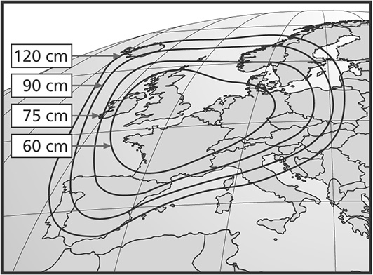
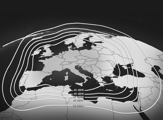
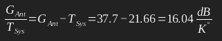
Calculations can be performed in both directions: either starting from the diameter value or using the dBW value to determine the corresponding diameter. For example, in the following example: Dish diameter of 120 cm corresponds to EIRP (Effective Isotropic Radiated Power) = 45 dBW Dish diameter of 75/90 cm corresponds to EIRP = 47 dBW Dish diameter of 75 cm corresponds to EIRP = 48 dBW Dish diameter of 60 cm corresponds to EIRP = 50 dBW Consequently, the footprints of the ASTRA and EUTELSAT satellites cover wide parts of Europe. Therefore, we will choose a parabolic dish with a diameter of 75 cm and an EIRP value of 48 dBW. After determining the EIRP values for both satellites and the diameter of the parabolic dish, the antenna parameters of the SAT-IP system, such as gain, bandwidth, beamwidth, etc., for transmission and reception were calculated. Since the SAT-IP antenna radiates in two directions, we need to determine the antenna sizes in both directions. Downlink to the SAT-IP Terminal (Forward Channel) After determining the diameter of the parabolic antenna, the antenna gain was calculated. Assuming a typical aperture efficiency of 70% or 0.7, the gain of such an antenna for the Ku-Band downlink can be calculated as follows.
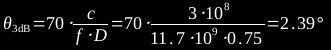
 The beamwidth of the parabolic antenna can be determined from the equation assuming a symmetric beam:
 The satellite signal on its way to Earth is subject to various sources of interference:

- Radiated power density of the satellite
- Free-space path loss from satellite to Earth antenna
- Atmospheric attenuation
- Rain attenuation
Uplink to SAT-IP Terminal (Return Channel)
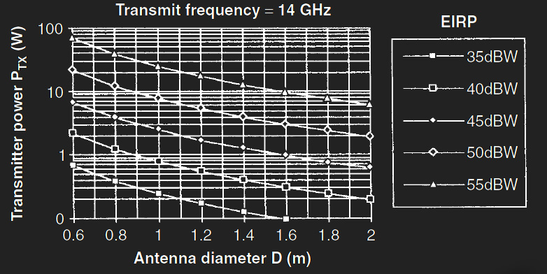
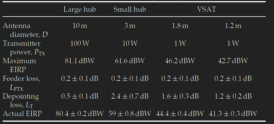
The following two figures and Table 1 have been taken from the book “VSAT Networks Second Edition.” From the lower figure, you can read the antenna gain calculations for frequencies from 4 to 14 GHz: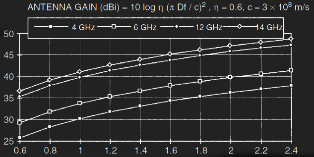
When selecting the substrates for the antenna elements, there is usually a compromise between cost, processability, and radio frequency (RF) suitability.
EANT GmbH and its partner, TU Berlin, agreed on a two-step material selection process. First, the material properties of the FR4 substrate were examined. If the losses in this material became unacceptable at higher frequencies, the HF substrate Megtron 6 would be chosen. Both materials are readily available and relatively cost-effective.
For assembly reasons, the casing should be manufactured in two shells that need to be joined and screwed together via a structured interface. Adhesives cannot be used in this location since most adhesives absorb water and could promote corrosion. At the same time, the casing must meet the requirements of electromagnetic waves and should only minimally attenuate them. Additionally, it is necessary to consider potential aging processes of the casing. A conventional solution involves using Teflon, but considering the intended dimensions, this would become extremely expensive, and its mechanical durability is relatively low. Within the collaborative project, alternative material selection and suitable sealing concepts are being explored to address these challenges while maintaining a compact form. Radome materials that meet both the required mechanical and electrical properties include glass-fiber-reinforced plastics (organic resins such as epoxy resins or polycarbonates).
EANT has a supply chain for simple plastic radomes as well as more complex fiberglass radomes with a foam core. During the work on the demonstrator, significant investigations were carried out regarding the more complex fiberglass radomes due to their superior RF properties.
Simulation results
Beschreibung des Designmodells
Results of the Simulation
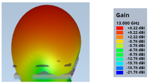
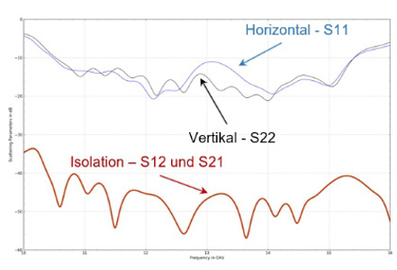
By decoupling the individual radiators, a significant improvement of the radiation characteristics was achieved. The results agree very well with the expected values.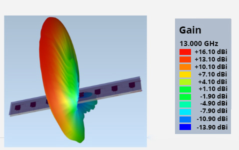
Design model description

Simulation results
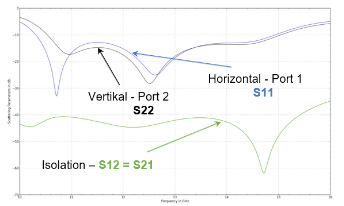
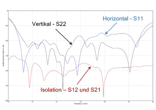
The simulation results for 1×16 elements also showed very good values. After optimising all parameters of the single element, several elements are combined into groups. Closely neighbouring antenna elements influence each other, which means that the composition of the individual elements has a great influence on the parameters of the group antenna. Step by step, elements are linked together and more are added.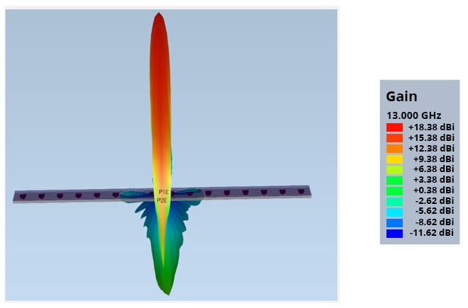
Together with TU Berlin, a construction concept was developed. The focus of our work package was the review of the concept and the selection of the Block-Down Converter and Block-Up Converter.
The receiving and transmitting modules are used for communication with a satellite with the aim of transmitting data for internet applications. These consist of three essential components:
- Antenna with high gain and narrow beamwidth.
- Block-Down Converter, abbreviated as LNB (Ku-Band to L-Band).
- Block-Up Converter, abbreviated as BUC (L-Band to Ku-Band).
Satellites transmit their high-frequency signals (payload signals) from orbit at approximately 36,000 km above the Earth to receiving antennas on the ground. Due to the long path to Earth, these payload signals are heavily attenuated. A converter, consisting of a series of components, is required for post-amplification and conversion of the high-frequency signal into the intermediate frequency range. Initially, the operation of a conventional converter, as found in every satellite LNB, was considered. In such a converter, there is a low-noise preamplifier (LNA), a mixer for converting the signal into the frequency range (mixer), an intermediate frequency amplifier (IF Amplifier), two local oscillators with low phase noise (LO), and two filters before and after the mixer.
A Down Converter (LNB) functions to amplify and convert the signals focused by the satellite reception antenna into a lower frequency range. The converted signal is then sent to a DVB-S2 receiver via a coaxial cable. The signal coming from the modulator runs through another cable to the Upconverter (including an amplifier). The Upconverter converts the lower frequencies into a higher frequency range and amplifies the signal using power amplifiers (PA).
All necessary switching functions for the operation of BUC/LNB (e.g., the “idle mode” of the BUC, LNB band switching) must be possible through the processor of the integrated modem. Desirable BUC functions include an “idle” mode controlled by the modem and low power consumption when not transmitting.
To preserve the signal-to-noise ratio (SNR), low-noise amplifiers (LNAs) are preferred in high-frequency and microwave technology. They provide the ability to effectively eliminate the additional noise caused by lossy structures by pre-amplifying the signal. With suitable design of the amplifier, this can be achieved with very little increase in noise figure, even for high losses.
The use of LNAs is an old, proven, and methodical approach for preserving signal quality at the input of a receiver structure. In the following design document, this method is also used to protect the received signal from the losses caused by the phase shifters.
Without the use of these LNAs, the losses in the phase shifters of the phased-array antenna would reduce the signal-to-noise ratio by the amount of their losses. Assuming a 4dB insertion loss through the phase shifters, this would result in a reduction of SNR by exactly 4dB. Based on EANT’s long-standing experience, the following converter was selected: Universal Ku-Band LNB: NJR2842SN – 10.75 GHz – 12.7 GHz.
The Satcom modem is designed to ensure reliable digital data exchange using TDMA (Time Division Multiple Access) technology. The goal is to provide high-speed broadband internet access with cost-effective end-user equipment that offers targeted additional services beyond basic internet access. At the time of working on this task, the focus was on supporting geostationary services. Accordingly, the iDirect X7 modem (Rx: 950 MHz – 2150 MHz; Tx: 950 MHz – 1700 MHz) was selected, which is a common and widely used platform.
Satelliten-Modem: iDirect X7
Link: https://www.idirect.net/products/x7-satellite-router/
This modem offers an OpenAMIP (Open Antenna Management Interface Protocol) interface for antenna control, which has been implemented and tested. It automatically transfers satellite parameters, including orbit position, downlink and uplink frequencies, and symbol rate, to the tracking receiver’s control unit. The interface supports both a serial connection protocol and an Ethernet interface. After extensive testing of the modem on the Telenor network with broadband services and the OpenAMIP protocol for antenna control, this task was completed. Since the OpenAMIP interface is a standardized interface for antenna control, the results of this task are also applicable to other SatCom modems and are not limited to the model used here.
Antenna Aperture and Connection to the RF Frontend
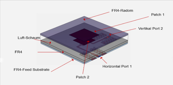
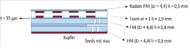
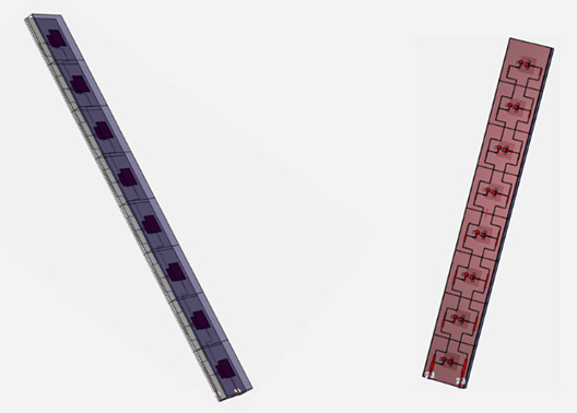
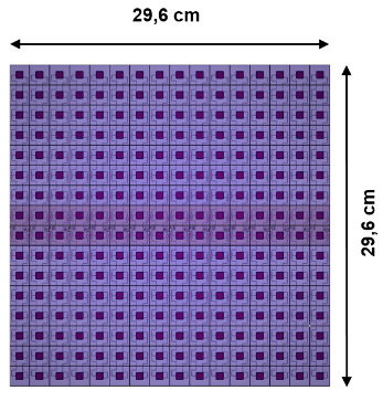
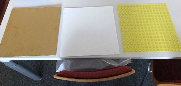
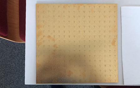
In the first step of manufacturing a functional prototype, the antenna structures (feeding, honeycomb core, and patch array) were initially manufactured separately. The honeycomb core is glued to the feeding network using epoxy adhesive and then connected to the patch array. The schematic structure is shown in Figure 19, and photos of the components are provided in Figures 20 and 21.
Mechanical Positioner
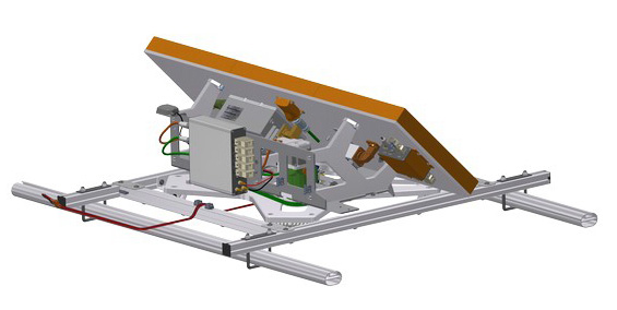
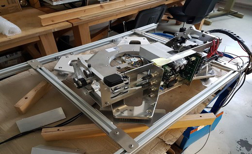
Next, the development and assembly of the mechanical positioner will be presented. The starting point for the positioner is the requirement to align the antenna aperture in azimuth with the satellite, as well as to provide all mechanical interfaces for electronic components and the aperture. Since the antenna aperture realizes tracking and alignment in the elevation axis and skew electronically, a mechanical drive was provided for alignment in the azimuth direction. The original “turntable” principle has been further developed into a belt drive with an additional gear stage.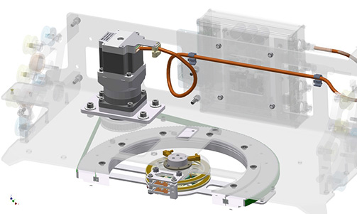 Driven by a stepper motor, this setup allows positioning in the hundredth degree range and provides sufficiently high acceleration (> 500°/s²) and speed (approximately 100°/s). With these values, the mechanical positioner is suitable for both maritime and land mobile use.
Furthermore, a 2-channel rotary coupling for high-frequency signals up to 2.5 GHz was provided, as well as 2 slip rings for the DC power supply of the electronic components. This setup allows unlimited rotation and positioning of the system in azimuth and the transmission of all necessary signals between the outdoor and indoor units (modem) via a terminal assembly integrated into the housing/radome of the system.
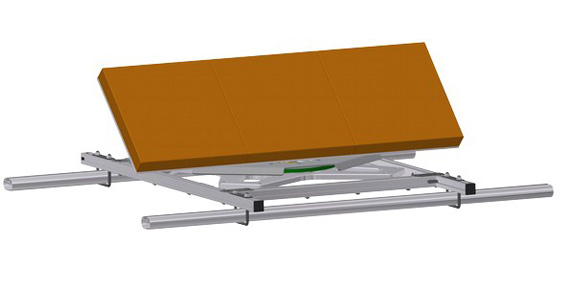
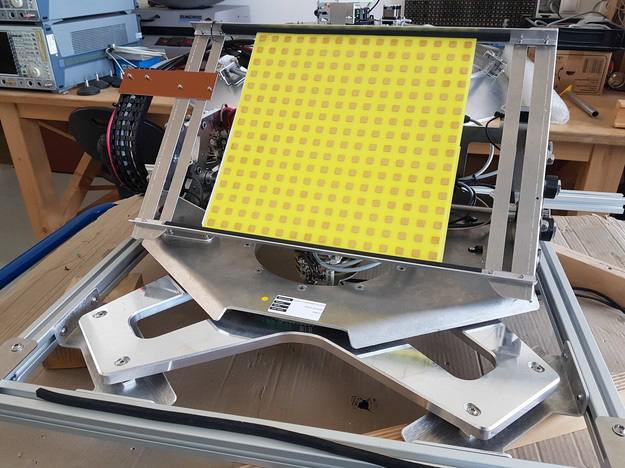
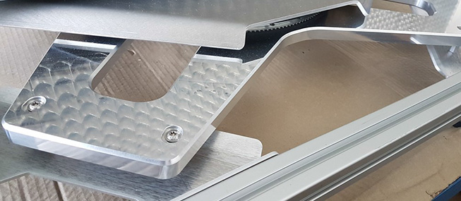
The mechanical interface to the aperture is formed by 2 milled parts that create a 45° angle to the baseplate of the positioner. While angling the aperture increases the profile of the system, it significantly enlarges the operating range of the antenna system for geostationary satellites, as lower elevation angles can be targeted. The positioner also includes mechanical interfaces for attaching the antenna control and an IMU (Inertial Measurement Unit).
The following illustrations show the CAD construction model, which serves as the basis for all derived construction drawings and the assembly of the positioner.
Driven by a stepper motor, this setup allows positioning in the hundredth degree range and provides sufficiently high acceleration (> 500°/s²) and speed (approximately 100°/s). With these values, the mechanical positioner is suitable for both maritime and land mobile use.
Furthermore, a 2-channel rotary coupling for high-frequency signals up to 2.5 GHz was provided, as well as 2 slip rings for the DC power supply of the electronic components. This setup allows unlimited rotation and positioning of the system in azimuth and the transmission of all necessary signals between the outdoor and indoor units (modem) via a terminal assembly integrated into the housing/radome of the system.
The mechanical interface to the aperture is formed by 2 milled parts that create a 45° angle to the baseplate of the positioner. While angling the aperture increases the profile of the system, it significantly enlarges the operating range of the antenna system for geostationary satellites, as lower elevation angles can be targeted. The positioner also includes mechanical interfaces for attaching the antenna control and an IMU (Inertial Measurement Unit).
The following illustrations show the CAD construction model, which serves as the basis for all derived construction drawings and the assembly of the positioner.
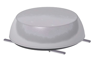
Gehäuse / Radom
In addition to the outer shape, the general structure and material selection were of great importance in the development of the radome. The material composition determines the strength, environmental, and high-frequency properties, and high demands must be placed on each of these properties. The antenna system is used exclusively outdoors and is exposed to environmental factors such as rain, wind, temperature fluctuations, and UV radiation. The high wind loads should only lead to limited deformations, and the structure must withstand wind speeds of up to 200 km/h. The attenuation values in the receive and transmit frequency range should be as low as possible, and the radiation pattern should be minimally influenced by the radome in every “line of sight” of the aperture.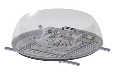
The tasks to be carried out in the context of WP8 include tests with the prototype to empirically analyze its characteristics and all necessary preparatory work. Fundamentally, these tasks can be divided between work and tests on the mechanical positioner and those on the aperture. Tests on the overall system primarily focused on mechanical mounting and integration, as well as tests on the electronic interfaces for controlling the aperture.
During the preparations for WP8, a significant change in the market situation for the technology developed in the project became apparent. This is detailed in the final report. Accordingly, this development influenced the definition of field tests and the work carried out, shifting the project’s focus more towards LEO constellations. However, the final parameters for gain, tracking range, polarization, and terminal calculation are not fully known and can only be partially estimated for this application. The EANT has been in discussions with constellation operators and partners to finalize these parameters. For instance, the requirements for polarization have changed to now include support for circular polarization. Initial estimates suggest that the necessary EIRP levels will be lower than those of common geostationary applications with comparable 45 cm reflector antennas. The frequency range of some prevalent constellations will fall within the specified range for the aperture.
Considering these circumstances, a single module was initially manufactured for the prototype, as it allows for flexibility in responding to changing market conditions. At this point, field tests with a satellite connection could not be conducted because such tests currently require proprietary hardware that EANT does not possess. The evaluation of the performance of the developed aperture module is conducted by the project partner, and the results are discussed in the final report from TU Berlin. Even with the altered requirements regarding suitability for constellations, the final evaluation of the aperture will be completed after the project.
Static and dynamic tests were performed on the mechanical positioner. To control the aperture, the existing antenna control system was expanded to include an electronic interface for aperture control. An EMC and EMI-suitable connection with differential line routing was specified and integrated in consultation with the project partner from TU Berlin, as well as tested. Alongside the selection of interface drivers, a transmission protocol was defined with predefined commands for transmitting diagnostic information and controlling the aperture. For instance, this protocol is used to set the elevation target angle and query the state of the antenna aperture.
All electronic connections and cables were assembled and then electrically and, where necessary, measured and tested on high-frequency measurement devices. It was ensured that the achieved reflection factors and transmission behavior allow for trouble-free operation.
To prepare for the tests, the mechanical positioner was put into operation in individual assemblies during assembly and final assembly. The result was that the motor control, in conjunction with the mechanical drive, achieved the desired characteristics. However, when driven with high accelerations and speeds, weaknesses in the torsional rigidity of the base plate and substructure of the system became apparent. These weaknesses were reworked and resolved as part of a redesign.
The algorithms for determining the antenna’s position and optimizing its alignment were expanded to support electronic deflection in the elevation axis. Since in mechanical optimization, the sensor system itself is deflected, and in electronic deflection only the main beam direction but not the sensor system (IMU) itself is moved, corresponding adjustments had to be made to the existing tracking algorithm. For this purpose, on the one hand, the model of the KALMAN filter for position estimation in sensor data fusion was extended with corresponding routines, and the motor control within the optimization routines was adapted to instead generate purely electronic adjustment. The routines for controlling the aperture and position estimation as well as signal optimization were tested and verified in laboratory setups.
Based on the described work, the predefined functionalities and specifications were compared with the realized characteristics. The results are presented in tabular form below. It should be noted that only a single aperture was implemented, and adjustments had to be made to accommodate a partially modified requirements profile.
| Parameter | Values according to specifications | Values reached in project |
| Size | 30 x 30 cm2 | 40 x 30 cm2 |
| Weight | <6 kg | <6 kg |
| Frequency range Tx | 13.75 – 14.5 GHz | 13.75 – 14.5 Ghz |
| Frequency range Rx | 10.7 – 12.75 GHz | 10.7 – 12.75 GHz |
| Max. Transmitting power | 39 dBw | 41 dBw |
| Max. Backflow attenuation | >10 dB | >10 dB |
| Antenna gain Tx | 33 dBi | 30 dBi |
| Antenna gain Rx | 33 dBi | 30 dBi |
| Half-width Tx | 2° | 2° |
| Half-width Rx | 1° | 1° |
| Angle resolution Tx (Phase shifter) | 1.5° | 1.5° |
| Winkelauflösung Rx (Phasen shifter) | 1° | 1° |
| Control range (Azimuth) | 360° | 360° |
| Control range (Elevation) | 60° | 60° |
| Polarisation | Dual (vertical/horizontal) | Dual |
| Temperature range | -20…60°C | 20…60°C |