Fiberlink:
a plug-in system that enables optical signal transmission

Development project Fiberlink
a plug-in system that enables optical signal transmission

Project description

Aim of the Fiberlink project is the development of a plug-in system that enables optical signal transmission while remaining transparent to the existing VSAT system and easy to integrate without significant effort.

The attenuation of coaxial cables steadily increases with their length. Even high-quality cables exhibit moderate attenuation in the high-frequency range at large lengths (e.g., ECOFLEX 15, approximately 15dB at 100m and 2GHz). However, due to their diameter and weight, they can be cumbersome to install and may pose a significant cost factor (2x 100m ECOFLEX 15 costs around 1500€). A common alternative in such cases is to switch to optical fiber cables. Furthermore, in modern installations on ships and offshore platforms, there is a growing trend to use optical fiber instead of coaxial cables.

The goal of the project was to develop a plug-in system that enables optical signal transmission but otherwise behaves transparently for the existing VSAT (Very Small Aperture Terminal) system and can be integrated without significant effort.

Fundamentals

Graphical representation of the outdoor unit of the fibrelink
Fiberlink – Outdoor unit

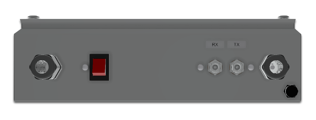
In normal operation (connecting the antenna using coaxial cables), one cable is required for TX (transmit) and one cable for RX (receive). The TX cable carries the supply voltage, transmit signal, and reference signal for the Block Upconverter (BUC). The RX cable supplies voltage to the antenna, transports the received signal from the Low-Noise Block (LNB) to the modem, and facilitates bidirectional communication between the antenna and Antenna Control Unit (ACU).

Since optical fiber cables cannot transmit power and, without complex optical signal processing, can only transmit signals in one direction, two separate devices are required:

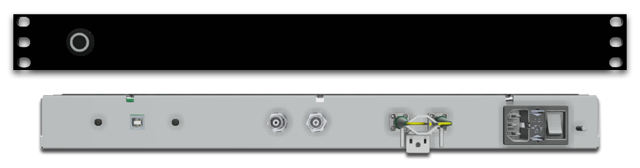
  1. Near the ACU, a device must be placed that splits the incoming signals (TX, RX, communication) into transmit and receive signals. The signals to be transmitted (10MHz – 2500MHz) are then converted into an optical signal, and the received signals are converted back from optical to electrical.
  2. Near the Outdoor Unit (ODU), a device must also be placed to perform optical-to-electrical conversion. Additionally, power supply for the BUC and ODU must be provided, and relevant measurements (current, voltage, environmental data) must be recorded and made available for the ACU.

Challenges

  • Since optical fiber communication operates in a simplex configuration (two cables that transport signals in only one direction each), communication between the ACU and the antenna must be split into its RX and TX components using a complex circulator circuit.
    The TX component of communication is then combined with the corresponding DVB (Digital Video Broadcasting) signal. A very high directivity of the circulator is required because even slight crosstalk from TX to RX (and large signal level differences of up to 40dB between TX and RX signals) or vice versa can result in a significant loss of signal quality and, consequently, proper functionality.
  • Since the outdoor unit must be placed in close proximity to the antenna, the top priority is that the housing is weatherproof, seawater-resistant, and that the internal technology is adequately protected. Furthermore, up to 400W of electrical power must be provided for the antenna (depending on size and the installed BUC).
    The converter losses of the integrated power supplies must be dissipated adequately even in direct sunlight and high ambient temperatures. Additionally, the system must function as intended even at outdoor temperatures as low as -20°C.
  • As the BUC and antenna are no longer directly powered by the ACU, there is a lack of measurements of current and voltage, which are important indicators of the proper functioning of the VSAT system. Furthermore, the voltage supply can no longer be controlled by software.
    To overcome these issues, an additional controller has been integrated into the outdoor unit, allowing remote control of the power supplies and recording relevant measurements (current, voltage, environmental data). This controller has been integrated into the communication channel between the ACU and the antenna.

Conclusion

Graphic representation of the ACU
Fiberlink – Indoor Unit

The system was developed by EANT under very challenging conditions (component shortages, the COVID-19 pandemic) within 6 months and was first installed on an offshore platform in the North Sea in early 2022. In test operation, no signal degradation is measurable, and the system behaves completely transparently for the installed VSAT system. Thus, a cost-effective and functional extension for optical fiber installations can be offered. 

On-site, besides a power supply for the outdoor unit (100V – 240V), it is only necessary to equip the pulled optical fiber cable with suitable connectors and connect it to the unit in the server room and at the antenna. Once the ACU and the antenna are connected to the Fiberlink, the system is immediately operational without further configuration.

Would you like to stay in touch with us?

Write us an E-mail or follow EANT on LinkedIn